Week 4 [Fri, Feb 2nd] - Topics
Guidance for the item(s) below:
In the tP, you'll be thrown into a codebase of about 6K . It would be hard to understand the design simply by reading the code. That's why the code base comes with a Developer Guide containing some design models i.e., the diagrams. That means, you should be able to interpret those models by the time you start the tP in a few weeks. 😨
Let's start getting ready for that today. First, let's go through a high-level explanation of models.
Can identify UML models
Unified Modeling Language (UML) is a graphical notation to describe various aspects of a software system. UML is the brainchild of three software modeling specialists James Rumbaugh, Grady Booch and Ivar Jacobson (also known as the Three Amigos). Each of them had developed their own notation for modeling software systems before joining forces to create a unified modeling language (hence, the term ‘Unified’ in UML). UML is currently the most commonly used modeling notation used in the software industry.
The following diagram uses the class diagram notation to show the different types of UML diagrams.

source:https://en.wikipedia.org/
Guidance for the item(s) below:
Now that we have a high-level understanding of the role played by models, let's start learning some UML models, starting with UML class diagrams (and object diagrams which are like a close cousin of class diagrams).
Note that we are learning to interpret these models only, not draw them (that would come later), or design them. Hence, we will be going through these topics fairly rapidly.
Can explain structure modeling of OO solutions
An OO solution is basically a network of objects interacting with each other. Therefore, it is useful to be able to model how the relevant objects are 'networked' together inside a software i.e. how the objects are connected together.
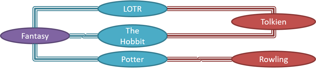
Given below is an illustration of some objects and how they are connected together. Note: the diagram uses an ad-hoc notation.
Note that these object structures within the same software can change over time.
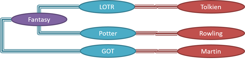
Given below is how the object structure in the previous example could have looked like at a different time.
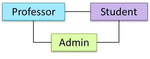
However, object structures do not change at random; they change based on a set of rules set by the designer of that software. Those rules that object structures need to follow can be illustrated as a class structure i.e. a structure that exists among the relevant classes.
Here is a class structure (drawn using an ad-hoc notation) that matches the object structures given in the previous two examples. For example, note how this class structure does not allow any connection between Genre objects and Author objects, a rule followed by the two object structures above.

UML Object Diagrams model object structures. UML Class Diagrams model class structures.
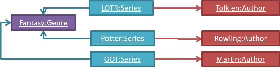
Here is an object diagram for the above example:
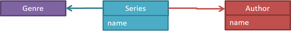
And here is the class diagram for it:
Can use basic-level class diagrams
Contents related to UML diagrams in the panels given below belong to a different chapter (i.e., the chapter dedicated to UML); they have been embedded here for convenience.
Classes form the basis of class diagrams.
Associations are the main connections among the classes in a class diagram.
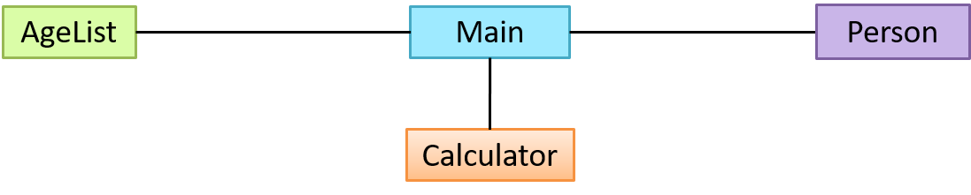
The most basic class diagram is a bunch of classes with some solid lines among them to represent associations, such as this one.
An example class diagram showing associations between classes.
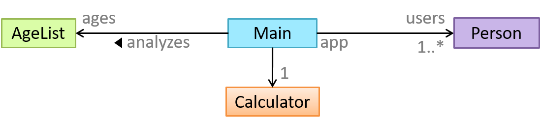
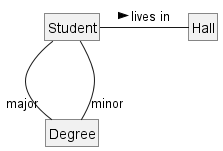
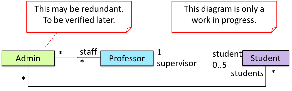
In addition, associations can show additional decorations such as association labels, association roles, multiplicity and navigability to add more information to a class diagram.
Here is the same class diagram shown earlier but with some additional information included:
Can distinguish between class diagrams and object diagrams
Compared to the notation for class diagrams, object diagrams differ in the following ways:
- Show objects instead of classes:
- Instance name may be shown
- There is a
:before the class name - Instance and class names are underlined
- Methods are omitted
- Multiplicities are omitted. Reason: an association line in an object diagram represents a connection to exactly one object (i.e., the multiplicity is always 1).
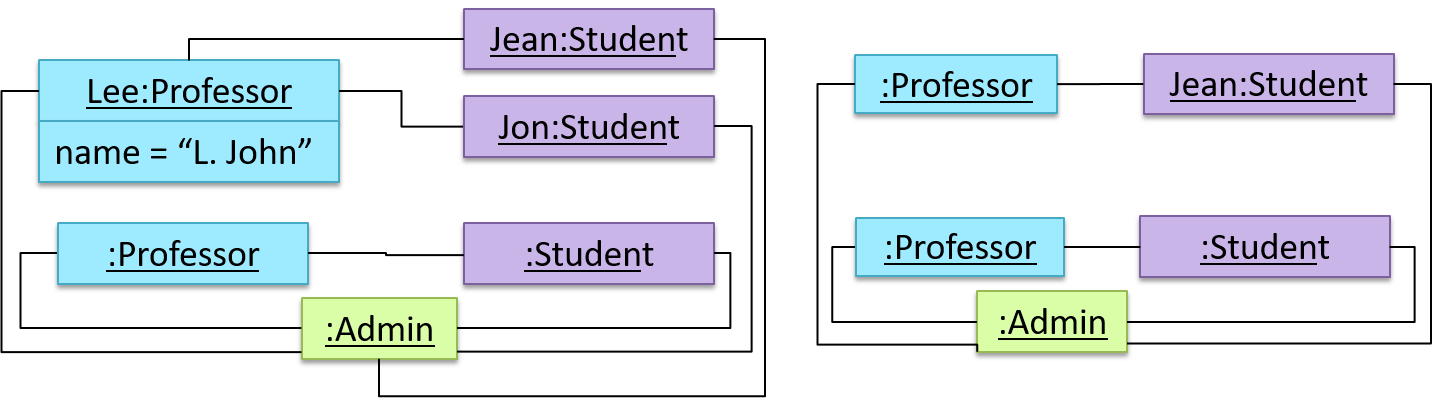
Furthermore, multiple object diagrams can correspond to a single class diagram.
Both object diagrams are derived from the same class diagram shown earlier. In other words, each of these object diagrams shows ‘an instance of’ the same class diagram.
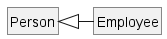
When the class diagram has an inheritance relationship, the object diagram should show either an object of the parent class or the child class, but not both.
Suppose Employee is a child class of the Person class. The class diagram will be as follows:
Now, how do you show an Employee object named jake?
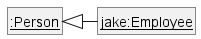 This is not correct, as there should be only one object.
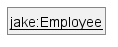 This is OK.
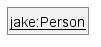 This is OK, as
 jakeis aPersontoo. That is, we can show the parent class instead of the child class if the child class doesn't matter to the purpose of the diagram (i.e., the reader of this diagram will not need to know thatjakeis in fact anEmployee).
Association labels/roles can be omitted unless they add value (e.g., showing them is useful if there are multiple associations between the two classes in concern -- otherwise you wouldn't know which association the object diagram is showing)
Consider this class diagram and the object diagram:
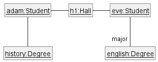
We can clearly see that both Adam and Eve lives in hall h1 (i.e., OK to omit the association label lives in) but we can't see if History is Adam's major or his minor (i.e., the diagram should have included either an association label or a role there). In contrast, we can see Eve is an English major.
Can interpret association classes in class diagrams
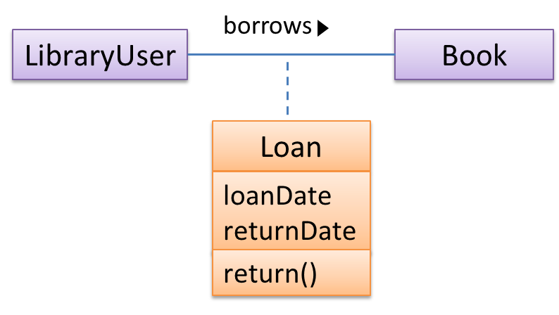
Association classes are denoted as a connection to an association link using a dashed line as shown below.
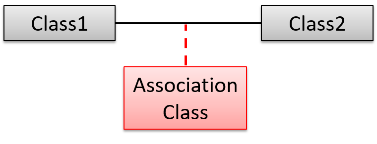
In this example Loan is an association class because it stores information about the borrows association between the User and the Book.
Guidance for the item(s) below:
Switching to Java now, let's learn how to write Java GUIs. Fair warning: GUI programming is hard in any language, especially so in Java. Buckle down and get through it; there's no way around it.
Guidance for the item(s) below:
While we are on the topic of Java, also take note of this is a lesser-known Java 'syntactic sugar' feature that was introduced not long ago, in case you come across it one day or find some use for it in your coding.
Guidance for the item(s) below:
Last week, we started learning about code quality. Let's continue on that, but learning a few other aspects of code quality.
Guidance for the item(s) below:
Next up are two techniques that can be used to improve code quality. You need to learn them as you will be encountering both in your iP soon.
Guidance for the item(s) below:
Being able to work with PRs is an essential skill. To get started on that, let's learn how to review PRs properly. Besides, you'll be doing some PR reviews in the iP this week.
Can review PRs on GitHub
The PR review stage is a dialog between the PR author and members of the repo that received the PR, in order to refine and eventually merge the PR.
Given below are some steps you can follow when reviewing a PR.
1. Locate the PR:
- Go to the GitHub page of the repo.
- Click on the Pull requests tab.
- Click on the PR you want to review.
2. Read the PR description. It might contain information relevant to reviewing the PR.
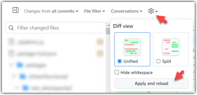
3. Click on the Files changed tab to see the diff view.
You can use the following setting to try the two different views available and pick the one you like.
4. Add review comments:
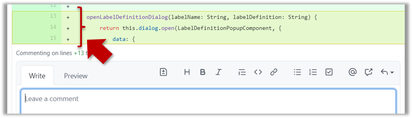
- Hover over the line you want to comment on and click on the icon that appears on the left margin. That should create a text box for you to enter your comment.
- To give a comment related to multiple lines, click-and-drag the icon. The result will look like this:
- To give a comment related to multiple lines, click-and-drag the icon. The result will look like this:
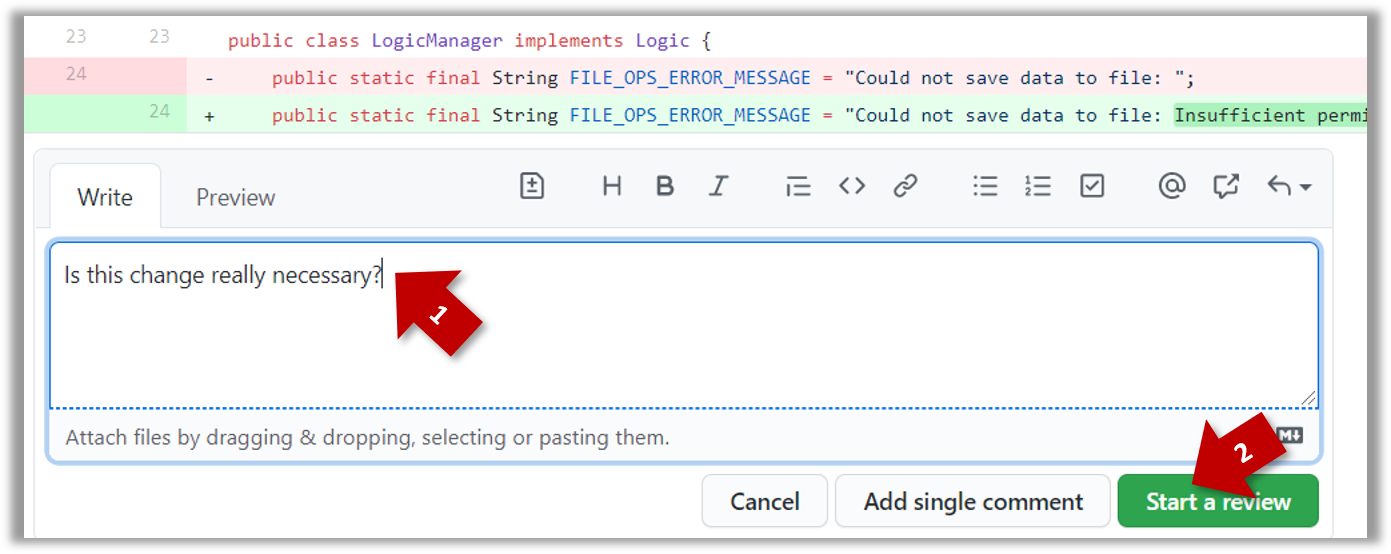
- Enter your comment.
- This page @SE-EDU/guides has some best practices PR reviewers can follow.
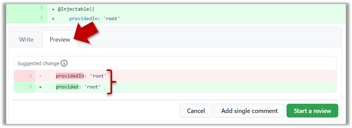
- To suggest an in-line code change, click on this icon:
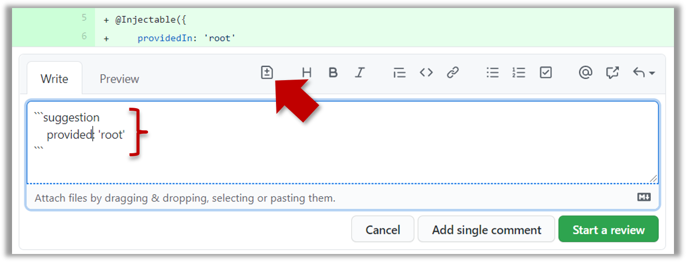
After that, you can proceed to edit thesuggestioncode block generated by GitHub (as seen in the screenshot above).
The comment will look like this to the viewers:
- After typing in the comment, click on the Start a review button (not the Add single comment button. This way, your comment is saved but not visible to others yet. It will be visible to others only when you have finished the entire review.
- Repeat the above steps to add more comments.
5. Submit the review:
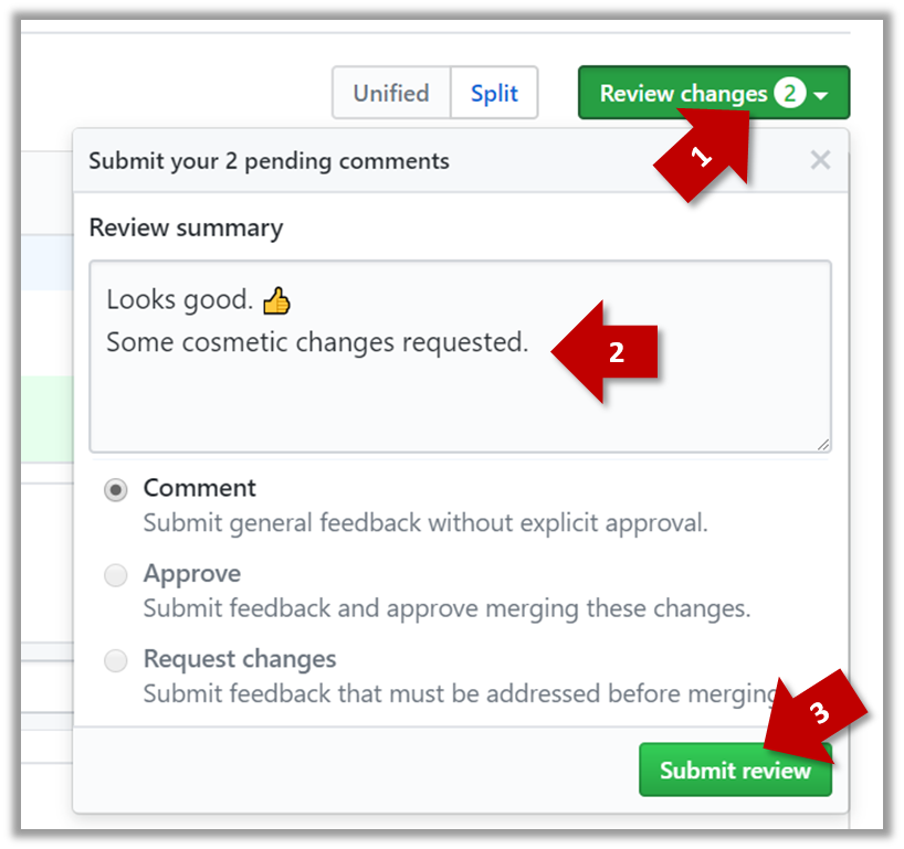
- When there are no more comments to add, click on the Review changes button (on the top right of the diff page).
- Type in an overall comment about the PR, if any. e.g.,
Overall, I found your code easy to read for the most part except a few places where the nesting was too deep. I noted a few minor coding standard violations too. Some of the classes are getting quite long. Consider splitting into smaller classes if that makes sense.LGTMis often used in such overall comments, to indicateLooks good to me(orLooks good to merge).
nit(as in nit-picking) is another such term, used to indicate minor flaws e.g.,LGTM. Just a few nits to fix.. - Choose
Approve,Comment, orRequest changesoption as appropriate and click on the Submit review button.